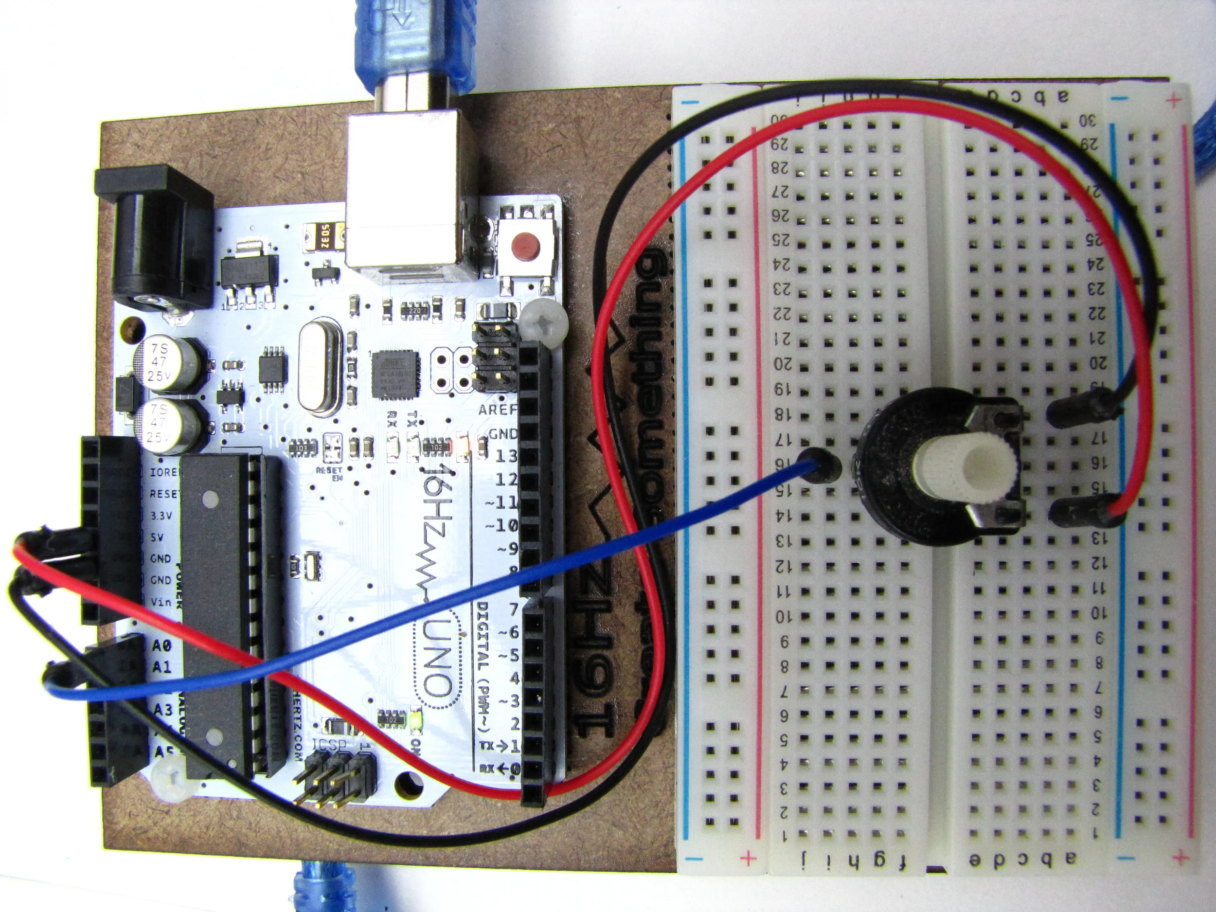
This Arduino and Board are set up to measure voltage at pin A0. Pins A0 to A5 are analog input pins. The red and black wires deliver 5 V from the board across a 12 K variable resistor that is grounded by the black wire going back to GND pin. The blue wire taps the variable resistor that acts like a voltage divider and carries a voltage to pin A0. As the variable resistor is twisted clockwise, the blue wire change voltage from 0 to 5 V.

Copy and Paste public domain program AnalogyRead from the Arduino website into you software window. There is the sketch window where all the programs are written and then downloaded to the microcontroller. To the right is a window the software uses to read information from the chip. In the software, Serial.begins start communication between the computer and the chip. The variable sensorValue is given the value of the voltage at pin A0. The value in memory variable sensorValue is printed on the computer screen to the right. It is a different window opened under the table Tools > Serial Monitor. The delay(1000), every second, allowed the print out to be slow enough for me to do a screen capture of the range from 0 to 5V. As I turned the resistor the values moved from 0 to 1023.