• Thomas Edison & Make Telegraph
  • Wisconsin Fast Plants
  • Rocket Science
  • Rocket Science
  • History of the Atomic Theory
  • DIY automatic bubble machined
  • Van de Graaf Generator
  • Two gallon aquarium
  • Chemistry grades 2-4
  • Crystal Radio Electronics 8-10
  • Wisconsin Fast Plant
  • Betta in a Bottle
  • My Prehistoric Creatures
  • Sea-Monkeys
  • Painted Lady Butterfly
  • Microworld Blog
  • K-2 Physics Experiments
  • K-1 Biology
  • Fun with Electricity K-1
  • New Cover Page
  • Science Project Classes Taught
  • Arduino Car Blog
  • Natural Born Scientists Store
  • About
  • Read Me
  • Home
Menu

Natural Born Scientists ®, LLC

Founded in 2008. Natural Born Scientists is a registered trademark
  • Thomas Edison & Make Telegraph
  • Wisconsin Fast Plants
  • Rocket Science
  • Rocket Science
  • History of the Atomic Theory
  • DIY automatic bubble machined
  • Van de Graaf Generator
  • Two gallon aquarium
  • Chemistry grades 2-4
  • Crystal Radio Electronics 8-10
  • Wisconsin Fast Plant
  • Betta in a Bottle
  • My Prehistoric Creatures
  • Sea-Monkeys
  • Painted Lady Butterfly
  • Microworld Blog
  • K-2 Physics Experiments
  • K-1 Biology
  • Fun with Electricity K-1
  • New Cover Page
  • Science Project Classes Taught
  • Arduino Car Blog
  • Natural Born Scientists Store
  • About
  • Read Me
  • Home
USB Microscope - 5MP interpolated 220x magnification / 8 LEDsPRODUCT ID: 636 $79.95http://www.adafruit.com/product/636Vividia Digital Microscope Universal Stand with X-Y Base and Built in LED Backlight $ 39.98  http://www.oasisscientific.com/di…

USB Microscope - 5MP interpolated 220x magnification / 8 LEDs
PRODUCT ID: 636 $79.95
http://www.adafruit.com/product/636
Vividia Digital Microscope Universal Stand with X-Y Base and Built in LED Backlight $ 39.98  
http://www.oasisscientific.com/digital-microscope-universal-stand.html


USB Microscope Allows Viewing on Laptop and Taking Photos and Videos

February 25, 2015
Comment
USB Microscope - 5MP interpolated 220x magnification / 8 LEDsPRODUCT ID: 636 $79.95http://www.adafruit.com/product/636Vividia Digital Microscope Universal Stand with X-Y Base and Built in LED Backlight $ 39.98  http://www.oasisscientific.com/di…

USB Microscope - 5MP interpolated 220x magnification / 8 LEDs
PRODUCT ID: 636 $79.95
http://www.adafruit.com/product/636

Vividia Digital Microscope Universal Stand with X-Y Base and Built in LED Backlight $ 39.98  
http://www.oasisscientific.com/digital-microscope-universal-stand.html

Recommended Microscope for Spring Class

February 25, 2015
Comment

Testing The Obstacle Avoiding Smart Car

February 23, 2015

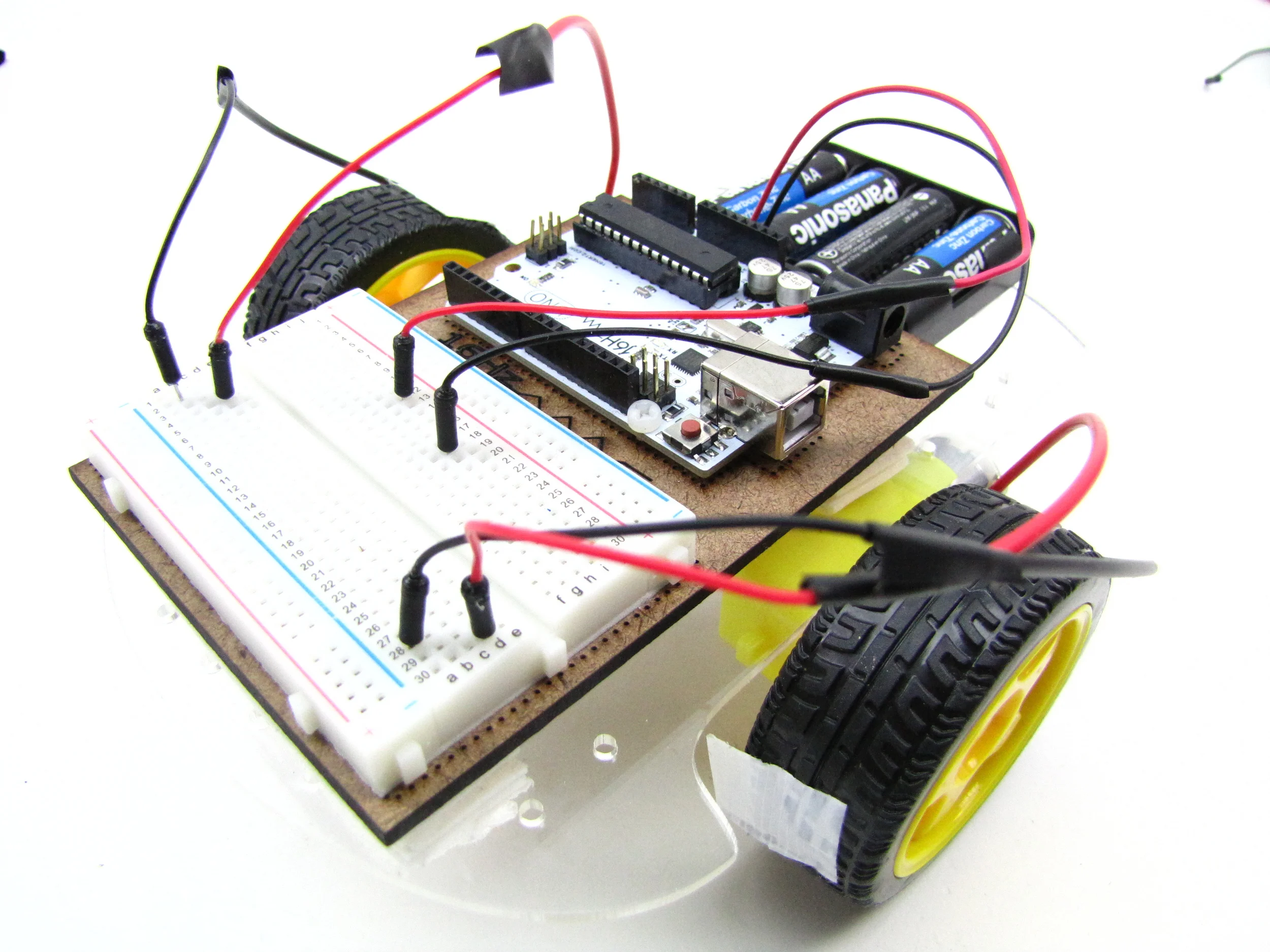
This is a test of the Obstacle Avoiding Smart Car. The original program had the stop and turn set at 6 cm in front of the car. As can be seen, it could not stop in time to avoid hitting the obstacle. It was changed to 12 cm in the next version. You may notice that the car just turned right. The left turn did not work because the program did not give it enough reverse time. That was fixed in the next version. But, this test demonstrates that the car worked in avoiding barriers and was found to be fun to watch.


Comment

The Obstacle Avoiding Smart Car, the final product from the Spring 2015 Super Saturday Class.

February 23, 2015

This is the final product from the Spring 2015 Super Saturday Class, the Obstacle Avoiding Smart Cart. The car is controlled by an Arduino Uno microcontroller with a motor shield on top to provide higher power to the motors. The smart car has three sonar eyes that constantly measures the distance to the nearest object in front, to the right at 45°, and to the left at 45°. When it sees an object at 12 cm or less in front it will turn right or left, whichever direction is the most open, and continue moving forward.  


Comment

Make your smart car travel in a zig zag pattern for practice.

February 10, 2015

RightLeftRightLeft. This program makes the car travel straight for 2 seconds, turn right for 0.5 seconds, straight for 2 seconds, turn left for 0.5 seconds, straight for 2 seconds, right for 0.5 seconds, straight for 2 seconds, left for 0.5, straight for 2 seconds, and finally pause for 1 seconds. The program was written in the void setup section so it will not loop. You can rerun it by pressing reset. Straight, right, straight, left, straight, right, straight, left, straight, stop. The turns were sharp turns with one wheel stopped and the other at fast speed. Experiment with the patterns.


2 Comments

Make your smart car travel in left hand circles for practice.

February 9, 2015

To make a left turn circle, modify the right turn circle program by switching the speeds of the right and left wheels making left wheel slower than the right wheel. Many of the students noticed that the wheels do not rotate at the same speed even if the speeds are set to the same number. Each motor has its own turn on threshold and it own response rate to the settings. 


Comment

Make your smart car travel in right hand circles for practise.

February 6, 2015

Make your car turn in right hand circles for practice. In the program above, the M1 terminal on the motor shield is named LeftMotor and the M2 terminal RightMotor. This program was written in the void setup() section, so it will only run once, i.e. not loop. However, you can make it repeat by pressing the reset button on the shield. The right motor is set at a lower speed than the left so that the car will turn in right circles. These motors don’t start turning until about 100/255 speed or about 2.4 V so the right wheel is turning slower than the left. The delay of 10000 millisecond will give the travel 10 second and then stop.


Comment

Modified Motor Test Program

February 5, 2015

The Motor Test program was modified to change the serial monitoring output message format and text, because I thought would be easier to understand for motor testing. It changes to text output to match the command name and prints them out with carriage returns so the text stacks on the screen. A space is also printed between each loop. The original program worked without the modification and this was changed for my preference, maybe yours. For some, this may be more of an example of Arduino coding practice than to produce a perfect program. Try it anyway, it will give you experience in the serial monitoring communication programming.


Comment

How to test your microcontroller, shield, and motor system

February 4, 2015

Test the microcontroller, shield, and motor system using the example program provided by Adafruit called Motor Test found in the AFMotor folder under examples. Only one modification is needed to use this program, and that is to change AF_DCMotor motor(4) to AF_DCMotor motor(1), since we are not using motor terminal 3 and 4. Once the program is uploaded and the motors active, make sure the command of forward matches forward motion of the wheel, backward matches reverse, and release matches pause. Also, make sure the motor speed ramps up and down. If so, your motor system is OK to move forward in the project. If not, adjust motor lead until these functions match the command. After this program, modify the program for motor 2 and repeat test. 

Comment

How to install AFMotor.h file from Adafruit to your computer for motor shield.

February 3, 2015

This video is how to install AFMotor.h file onto your computer to be used by the Arduino IDE software in programming the Motor Shield that controls the smart car motor. At the lower right corner of this video is a link to view the video directly from YouTube. The print is small, so viewing it from YouTube and expanding the screen will help see the key stroke movements.


Comment

Motor Test Program Video

January 27, 2015

This video shows the results of the Motor Test program. The Arduino is now controlling the motors and wheels through the motor shield. The wheels rotate forward for a second, reverse for a second, and pause for a second, moreover at each task the software sends text to the IDE software monitoring window and then keeps looping through these tasks. This program will test your system. Do the motors all rotate in the same directions indicating the polarities were wired correctly. These command will be used in further programs.

Comment

Writing a Program to Test the Shield and Motors

January 27, 2015

The company Adafruit sold the L293D motor shield kit that is now obsolete, but they still provide its learning documentation, Adafruit Motor Shield, at https://learn.adafruit.com/downloads/pdf/adafruit-motor-shield.pdf and the assembled board can be purchased elsewhere. This test program above came from this reference, please refer to it. The AF_Motor Arduino library (AFMotor.h) must be installed to instruct the Arduino how to talk to the Motor shield. Follow the Adafruit instruction on how to install it into the Arduino IDE. Then, copy, paste, and upload this test program to your Arduino and test your car.

Comment
The batteries are connected to +M and GND. Left and Right motors are connected to terminals M1 and M2.

The batteries are connected to +M and GND. Left and Right motors are connected to terminals M1 and M2.

The Batteries and Motors are Connected to the Shield Not the Arduino

January 26, 2015

The motor shield can control four motors, but this car only uses two motors. This picture shows the left motor connected to the M1 terminals and the right motor connected to M2 terminal. The battery pack is connect to the external M+ and GND of the motor shield, not the Arduino. The power to the Arduino now comes through the shield


Comment
L293D motor shield fitting into the pins of the Arduino board.

L293D motor shield fitting into the pins of the Arduino board.

The Motor Shield Inserts Directly into the Arduino Board

January 26, 2015

The Motor Shield sits on top of the Arduino board with connecting pins going down to the Arduino. The pins have to line up exactly to work properly. This picture shows the pins lining up, however the shield must be pushed down tightly once the pins are lined up exactly.

Comment

The Motor Shield Made with L293D Chips

January 26, 2015

The L293D Motor Shield can be used to power up to four motors. The motor are connected to the motor shield instead of the Arduino. The batteries are not connected to the shield. The shield contains two L293D chips that can control up to 600 mA of current by programming the Arduino.


Comment

Adding Arduino Brains to the Acrylic Chassis

January 26, 2015

Add brains to the car by mounting the Arduino and breadboard on top of the acrylic chassis. Eight layers of mounting tape between the acrylic and board will bring the USB port above the wheel level. The Arduino microcontroller cannot handle anymore that 40 mA of electric current. The motor uses 100 to 200 mA of current, and will burn out the microcontroller if one tries to run the motor from one of the Arduino pins. A motor shield has to be used between the Arduino and motors, and this can handle up to 600 mA of current. 

Comment

Testing the 2WD Chassis Without Microcontroller Control.

January 24, 2015

The 2WD chassis was assembled and tested. No microcontroller was used at this point to control the car, Just the car chassis was tested. The microcontroller and breadboard were programmed separately to send SOS by LED. Next step will be to link the micro-controllers to the motors and program its route.

Comment

The 2WD (wheel drive) Smart Car Chassis Assembled and Running

January 22, 2015

This is a video of the assembled “2WD smart car chassis” without the Arduino microcontroller. Jumper wires obtained from the Arduino starter kit were cut, soldered, and taped onto the motor and battery leads adding plugin pins for the breadboard. The wires were then connected using a breadboard. Tape was put on the wheels to observe there rotation of the wheels. Note that the wheel do not turn at the same rate. When placed on the floor this car runs in circles like a chicken with it head cut off without the Arduino controller and that will be added next.

Comment

The 2WD Smart Car Chassis Kit

January 22, 2015

The 2WD (2 wheel drive) smart car kit can be purchased from Ebay for $14 with free shipping from China if one can wait for 9 days. The kit contains all the parts needed to build a 2WD dumb car, since there is no microcontroller. The body is clear acrylic sheet that comes with protective paper that can be removed during construction. The kit comes with assembly instructions in Chinese with pictures. The pictures along provide enough direction to assemble the parts. The motor gear shafts were oiled to reduce friction.

Comment

Experiment 5: Blink 14 program.

January 20, 2015
Comment
Older Posts →

Harness the power to shape our future by inspiring and educating the next generation of scientific minds. With just a simple act, you can profoundly influence the trajectory of young inquisitive souls. Dive into this mission with us: By contributing to the link below, you're not just donating; you're investing in a brighter, scientifically-enriched future. Your support can be the catalyst that ignites a lifelong passion for science in countless young hearts. Join us, and together, let's mold the innovators of tomorrow.

Natural Born Scientists' PayPal

Classes offered through the Super Saturday Program (www.supersaturday.org) to children in the tristate area


Taught through the

Super Saturday Program

www.supersaturday.org


This 6-Saturday course studies electricity through projects followed by lessons explaining the projects.

Powered by Squarespace